Showing posts with label wiring. Show all posts

Thursday, 26 February 2015

The End is (Al)Most Definitely Nigh…

…accelerated by the magic of electricity.  I need to now start making plans for the Little Goose as she will be nearing completion soon.   

  IMG-20150225-WA0000 IMG-20150225-WA0001

The rear light is in a rough position but all lit up along with nice wiring blocks also to the rear indicators…

IMG-20150225-WA0002 IMG-20150225-WA0004

…the taping up continues apace…before and after shots…

IMG-20150225-WA0003

IMG-20150225-WA0005

Working methodically from rear to the front of the bike with the fabric loom tape…

 IMG-20150225-WA0006 

The clocks have come off to make the final bit of wiring easier and tidier.

 IMG-20150226-WA0003

Tape loom and shrink wrap applied…

IMG-20150226-WA0004

…and applied to the LEDs of the dash lights

IMG-20150226-WA0005

Much tidier.

IMG-20150226-WA0006

…and finally another 10 second video of lights and sound…


All being well tomorrow should see the brakes completed and mounting holes drilled into the seat pan.  Then Saturday I will be taking said seat pan to an upholsterer’s to see if they can make the seat how I want it…watch this space.

Sunday, 22 February 2015

(Dash) Lights…(My) Camera…(In)Action….

…for now at least.  The wiring is moving at a pace thanks to my brother-in-law Leon…a completely new loom is taking shape with wires that match the colours on a great A3 sized Guzzi wiring diagram I have compared with the random colours used in the botched loom. 

20150220_194118 20150220_203618

20150220_203959

This is where the main loom joints together front to rear…

IMG-20150218-WA0002   IMG-20150212-WA0002

…some tidying required around the back of the headlight bowl as this is temporary to check that everything works…

IMG-20150222-WA0002

…which it does!  This is an Osram Nightbreaker bulb and is brilliantly bright.

IMG-20150218-WA0001 IMG-20150218-WA0000

The dash is coming on also…the clocks are back lit but are quite dim so will look at changing them to LED’s if possible.

20150220_194127

The dash LED’s are are super bright, particularly the High Beam.  Both the indicator dash lights are working and the Neutral light leaving only the Ignition/Charge light to wire in.  The front indicators, with their LED’s are working just fine…

 IMG-20150222-WA0000 

…leaving the rear Stop/Tail light and the rear indicators to wire in and that should just be about it for the wiring loom.  It will then be wrapped in fabric wiring tape to keep it all neat and tidy as well as protected from moisture and grime.

IMG-20150222-WA0003

One of the jobs left to do is to de-link the brakes as I mentioned in a previous blog.  So the nice people at HEL made me a brake line up that would do the job…except for the fact I forgot to specify a 90° bend in one of the unions…doh!  So I have now ordered another brake line but this time from Venhill (remembering the 90° bend!) whose unions are screwed onto the braided line rather than swaged on like the HEL ones meaning they cannot be removed successfully by someone at home.

Jobs to do…

  • Fit the brake line when it arrives and put fluid into the braking system and bleed.
  • Balance the carburettors.
  • Check the nearside fork seal, as it wept when tied down on the trailer…too much compression!
  • Commission a new seat for the old seat pan…below is my preferred option seeing as I cannot go Street Tracker with it due to the tyre cut out in the seat pan…safety over aesthetics.  I have ordered a 20cm square of race seat foam that I will stick to the bare seat pan to get it to the MOT (Ministry of Transport) safety testing station.

brown hump

  • Check all nuts and bolts…add medium strength thread-lock, then torque tight.
  • Bin the current fuel pipes with their crossover and run a single fuel hose from each carburettor to each fuel tank tap.
  • Take it for its MOT test…job done.

Sunday, 15 February 2015

Elecktrickery, De-Linking & …Progress.

Well this was a quite unexpectedly early blog to be making seeing as the wee Guzzi has only been at its temporary home for just over a week.  But, how things move on when you know what you are doing.  Of course the ‘you’ to whom I am referring is not me but said Electro-God brother-in-law!

Once my girl had settled into her temporary abode she was disembowelled of the rats nest of wires that had masqueraded as a wiring loom.

20150210_182020

Now that mess is being replaced with precision, care and attention to detail…

 IMG-20150212-WA0001 IMG-20150212-WA0000IMG-20150212-WA0002 …by someone who knows what they are doing.

The previous owner of the bike had continued with the quirky (flak jacket donned!) linked brake system Guzzi bestowed upon the V50 but had upgraded the master cylinder with a handlebar mounted one that on inspection is going to unbalance the brakes as it is so much more powerful than the original frame mounted cable operated gubbins.  The Brembo bar mounted master cylinder is expensive especially as it required a new lever and clamp…probably around £170 ($260)…so rather than replace that we are going to de-link the brakes.

The original Moto Guzzi system has the brake lever operate one front brake caliper whilst the foot brake operates the other front brake caliper plus the rear caliper in order to evenly distribute braking and enhance stability under braking.  On the rear brake master cylinder there is a banjo splitter one side of which sends brake fluid to the rear caliper via a short braided hose whilst the other sends brake fluid along some copper brake pipe which then connects to braided hose to one of the front calipers. 

rear mc

SPLITTER

double banjo plug

So the plan is to remove all of the copper piping and place a blanking plug in the corresponding connection on the banjo splitter seen above.  Given the angle of the screw in brake light switch it seems easier to blank off one side of the splitter than go for a single banjo that would present problems when attaching the side panel.

Up at the handlebar mounted master cylinder a double length banjo to allow two braided hoses from both front calipers will be inserted into the master cylinder separating the front brakes from the rear as in a conventional braking setup. 

double banjo close up

I am aware that it is likely that the rear brake will become quite hard as it is only actuating one caliper as opposed to two so I may choose to go to a smaller capacity rear master cylinder if I can find one that has 50mm mounting hole centres.

The ignition wiring circuit is complete now, although the routing and taping up of all the wires will still be needed.  So whilst the lighting circuit is being worked on, below is a quick video showing how with some fuel the Little Goose would come to life!


Saturday, 15 November 2014

The Battle of the Wires Has Been Lost…

But I shall win the War!  This little Goose will live.  Eventually.  Not this year though.  Probably…

I am afraid to say that after wiring everything up, somewhat optimistically, in what I suspected might be the correct order, the moment came to turn the ignition key and fire her up.  That moment was captured forever on video as absolutely nothing happened….oh I did blow a fuse but don’t think that really counts.  I don’t understand this wizard’s magic called electricity and cannot make head nor tail of the rats nest of wiring that has been hacked about by various owners over the past 35 years. 

So this is how the bike looks today and is unlikely to look any different in the coming months…

20141101_091922   

I have two options at the moment…let my brother in law who ‘knows about these things’ have a look and a go with it or it gets shipped off to an electrickery expert.  Both options will require a new loom I think.  So that’s as far as I can go at the moment.  The next job to tackle is shortening the throttle cables due to having clip-ons rather than the raised bars that were originally in place and taking my slightly rough soldered dash LEDs off and putting new ones in that can be properly connected.

One piece of good news is the lovely shiny almost new motorcycle trailer that I got today in preparation for the need to take the bike to an electrician or more likely so someone can bring me home when it stops working miles from civilisation.  Once it starts working of course!

20141115_140401

Once all that is done then it will be the commissioning of a nice leather seat, topping up the fluids, bleeding brakes, ensuring everything is tightened up correctly and then just maybe she might be able to turn a wheel under her own steam.  In Springtime!  Maybe Summer!  Definitely not next Winter…

Friday, 18 April 2014

Grinding, Crimping and Snipping…A Trio of Firsts.

A solid eight hours on the bike this week due to taking a day off work to eek out the Bank Holiday weekend.  Obviously the wiring is still an ongoing best guess situation but I managed to change all the connectors for the left side switchgear (lights, horn, etc) along with their corresponding partners on the main loom.  I have a great colour A3 wiring diagram as I have mentioned previously so when I popped open the original ‘Lego’ switchgear I could see that all the wires matched and went where they should.  So…the first snip was to remove the original switchgear…no going back from here.

20140417_085506  20140417_091527

Old switch and new switch.                         Contemplating the cut….

20140417_091538   

Wasn’t so bad after all.

After removing the original switchgear I cut off all the connectors on the loom and the new switch and replaced them with brass bullet connectors.  Now I know a lot of people don’t generally like them but I have found these ones really good with a great tight fit and were simple and quick to crimp closed on the wires.  I used some heat shrink insulation over all the connectors…which I didn’t get a photo of…doh!  Rather I got one of the heat shrink being applied.  Woohoo!     

20140417_091521 20140417_094507 

 20140417_094828(0)  20140417_110725

…and the next bunch!               

As an old bike chunks of the wiring had been replaced over the years, making the following of the wiring diagram difficult.  For instance one set of four wires, shrink wrapped, were all different at one end of the run to the other and when they entered a connector block they were all different colours again the other side!  None of which matched the original.  This is going to be difficult to work out.  I have managed, by process of elimination plus some guesswork, to wire up the rear indicators and separate the tail/stop lights.  On the switchgear I have three or four wires I am not sure about as the wiring diagram that came with the switchgear is not very clear and the new switch has a separate pass and horn, rather than the combined tilt switch on the original switchgear which has resulted in more wires on the loom and less on the new wiring.  My brain had reached meltdown after eight hours so that conundrum will be left for another day.

Some decisions were made with regards the seat too.  Originally I had decided to just go and buy a custom made seat for about £175 in the flat tracker/brat style that I wanted.  However, a trip through YouTube made me consider building my own by chopping about the original seat pan.  I have since binned that idea given the shape of the pan rising at the rear and I want a very flat seat. 

 20140114_174436

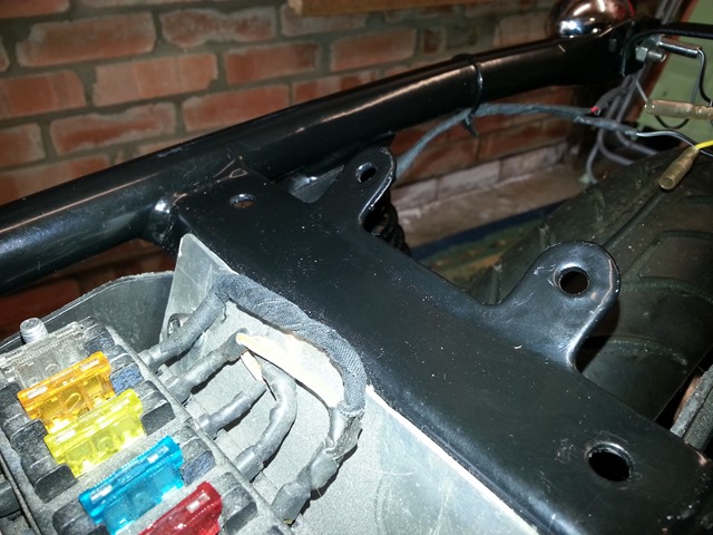
My father’s neighbour, who blasted the tank, fabricated and welded in the petrol cap and then powder coated it all for nothing (top bloke Lee!) has offered to make us a seat pan out of alloy.  This will clearly be a better job than I could do and will be cheaper as I don’t have the correct tools to be cutting and shaping alloy sheet.  So the plan is that a flat alloy sheet will be the basis of the seat which I will then take to a local upholsterer to get an idea of their ability to make what I require and within budget.  With that decision made I used an angle grinder for the first time to lop off a couple of lugs on the frame to allow the seat pan to sit flush on top of the frame rails as the lugs protruded above the frame.  Once ground off the bare metal was painted.

20140417_150321

Before…

20140417_151712

…and after (but before filing and paint).

20140417_154303 20140417_154318

All in all, I am happy with the way things are going although there is still a lot more to do with the wiring taking up the bulk of the next few months.  To break up that brain freezing complexity, I shall wrap and put the exhausts on in the near-ish future.  Feel free to comment or advise!