Saturday, 21 June 2014

Wrapping, Shiny Bits and Yet More Wiring To Redo!

Exhaust wrap…sets off the cafe racer quite well so I thought I would have a go at it.  Turned out not so bad actually.  I went for the pale coloured wrap thinking that there’s enough dark colour on the bike as it is.  I watched a couple of tutorials on YouTube which recommended soaking the wrap in water before applying it which is where I started.  A word of warning though…exhaust wrap is made of fibre glass so best not to wear shorts and have it trailing across your bare thighs!  Itchy doesn’t come close!

20140615_105150   20140615_105212

Getting the collets in correctly first time around would have helped this task!  Much wiggling and manoeuvring managed to get it on okay; having an extra pair of hands helps greatly.

20140615_105955   20140615_122851 

Gutsibits provided me with a lovely shiny polished surround that comes with 6 LED’s.  I originally got the pre-drilled surround but the holes were 70mm on centre apart rather than the 60mm needed for my V50, so I sent it back and got the undrilled version.  Obviously this meant that I would be drilling this £140 piece of billet…gulp!…still I had the experience of doing similar to the rearsets so a friend of the family allowed us to use his pillar drill and super bits that drilled the holes beautifully.

20140615_100125 20140621_131341

The clocks were a little ratty looking so a bit of primer and some more Satin Black and lacquer and they look almost new.

20140616_124656 20140616_124701 20140616_124839

As I was replacing the original filament bulbs for LED’s there was quite a bit of snipping off large spade connectors and swapping them for mini spade connectors.

20140621_114004 20140621_114009

The LED’s have what looked to be mini spade connectors but are actually ‘solder tags’.  Being a highly un-proficient solder-er I wondered if some mini spades might fit which they did but they are not a tight enough fit so will have to be chopped off again and soldered!  I think a thin piece of card between the ‘solder tag’ and the plastic body at the bottom of the LED will prevent me from melting it!

20140621_131347 20140621_131359 

20140621_131424 So the soldering iron will be coming out next week with a bucket of hope also!

20140621_135529 20140621_135559

 20140621_113446 20140621_113431

So after the re-doing of this bit of wiring I shall solder next week and then it will be a case of sorting the throttle twist grip out so as to stop the cables moving excessively.  Then, with a bit more wiring, I hope that within the next 6 – 8 weeks we can be adding fluids and try and fire it up for the first time!  Stay tuned…

Saturday, 24 May 2014

Welding…Looks easy doesn’t it?

Today a couple of other things have been crossed off the Job list. 

20140524_113914

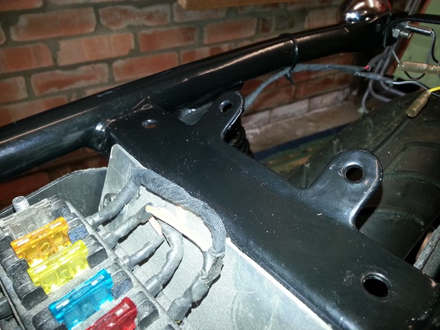
The new fuse box that the previous owner had installed has had to fit within the tool box/rear inner fender however the edge of this pushes against the connectors, popping them off of the terminals at times.  So I have got the Dremel out and removed a wide chunk of the box so the connectors don’t foul the box.

fusebox

The other job was to fit the oil breather system.  Again the previous owner made his own box up to do this job which I had previously cleaned up and painted.  So I have used some new rubber tubing and stainless Jubilee Clips and managed to connect it all up.  There were two tubes from the valve covers, one return to the sump and one that vents to the atmosphere.

20140524_101251      20140524_105711

 20140524_105649     20140524_105642

Clearly there is still some tidying up of wires…like finding where they go for starters!  The GEL battery I have is nice and slim so will still be sited correctly.  Pleased with getting this done both my dad and I decided to have a crack at welding as we have been lent a welder for the purposes of securing the bolts to the seat pan before it gets upholstered. 

20140524_110331   20140524_110402 

These two are my first ever efforts at welding…what a mess!!!  Melted the bolt head quite nicely though! 

20140524_111604    20140524_111643

The molten mess on the right hand bolt is my father’s first attempt at welding….hmmm!

20140524_111936    20140524_111944

Pretty sure we will get some kind of professional to do this as it really is harder than it looks!

The next instalment is likely to be some more wiring…perhaps wiring the starter button in preparation of starting this Goose up sometime in the next few weeks.

Saturday, 17 May 2014

New Winkers, A Seat Pan and A GOAT!

The seat pan has now been cut from 3mm stainless steel sheet, holes drilled and powder-coated from the flimsy cardboard template I provided.  And what a good job my helpful friend has done…thanks Lee!  When I first saw the seat pan it reminded me of smoked glass coffee tables from the 1980’s!!

20140517_095848 20140517_095917

For some reason the special bolt welding machine couldn’t get on with this bit of steel.  I will either use the marine grade M8 bolts that I have and to secure them I will either use a half nut directly under the pan (as the bolt will not be accessible once the seat is upholstered) or get the head of the bolt welded.  It won’t be seen as it will be covered in foam and a lovely tan coloured Tuck n’ Rolled seat.

In the previous blog I mentioned how the number plate was going to partially obscure the indicators so got a 3 line number plate made up to get around that problem.  However, the thread of the indicators was unnecessarily long when compared to the stem so I bit the bullet and got some new indicators with a longer stem/shorter thread.  Now the thread does not intrude into an area where the tyre could enter and I am happy enough with the distance between them with regards to safety…the have LED’s in them.

20140517_095627 20140517_095634  

I also have got the rear light bracket/number plate mount back which is powder-coated but think my measuring skills with regards the positioning of holes were on holiday as can be seen by the jaunty angle!  This was mostly rectified by reaming out one of the holes and making it slightly elongated…this helped!  It looks worse than it is due to the fact that it was not tightened up.

20140517_110638 20140517_110644

Double sided tape helped me mock the plate up.  Due to the extra width of the winkers I have decided that a standard sized 2 line number plate will be used as it will also help clear the rear tyre.  I shall keep the 3 liner for posterity!

20140517_110828 20140517_110810 A slight change in angle will help with clearance.  Being only 3mm sheet I should be able to bend it up a little to follow the angle of the tyre…but as a dry run it looks alright.

20140517_111159 20140517_111718

20140517_111803

20140517_112032 …and with an 8 year old boy aboard!

Oh…and here’s the GOAT!  An award for the “Best Renovation 2014” on the GB Bikers Forum.  Really nice to get some recognition for this steep learning curve I have been on for the past eighteen months.

20140514_161806

Thursday, 8 May 2014

Cardboard Fabrication!

Well the last session I have had with the little Goose was to find some solution to the number plate, rear light and seat conundrum.  After much rumination, expert judgement and a lot of guesswork a solution was found!  Hurrah! 

The problems were what kind of seat could I have without making too many compromises that would allow me to have the number plate in the right position.  However, a standard sized UK number plate’s width would foul the rear indicators.  Additionally, the rear light with integral number plate holder I had bought was not going to be part of the solution.  So that was £25 not very well spent.  The problem was that what I had purchased was probably meant to be sunk into the rear of a seat or ‘Frenched’ into bodywork somehow as the rear terminals weren’t encased in an aesthetic manner which you should be able to make out in the next photo with the old seat pan.

20140426_111604

Although the old seat pan looks okay it doesn’t suit a slim seat in a flat tracker/Brat style plus the rear lights wouldn’t look right because of the issue stated above.  So the old seat pan went back on the shelf.

20140426_111616

Out came the cardboard in the shape of a fish tank box!….and some rough lines drawn upon it following the lines of the frame.

20140426_100109 20140426_100726

Ah!  This was now looking better for the progress of the seat.  So much so that I had splashed out on another rear light, but this time it was in its own casing and would mount on a mudguard or bracket in some way.  As I referred to earlier, the standard UK number plate mounted at the right height/angle so as not to foul the rear wheel, would partially obscure the indicators by about 5mm each side.  I could mount it a little further down a yet to be made home built bracket but the angle would be more horizontal than vertical as per the MOT tester’s handbook.

20140426_113530 20140426_113538

Having seen regulations that state that motorcycles registered before Jan 1 2001 were eligible for 3 line number plates that’s what I decided to go for.  There is still a bit of a grey area associated with this which I won’t bore you with….so the solution was a flat seat, new bracket for a new rear light to mount to and a slimmer number plate…

   20140503_112822      20140503_11224920140503_112253     20140503_112243

Thankfully the kind neighbour that sorted the petrol tank out has offered to fabricate the seat pan and number plate bracket and powder coat them both….for nothing again.  This kind of support and expert help is invaluable. 

I have revisited my job list and the next job will be fit the clutch cable before routing it gets too difficult and fit the oil breather tank in place and cut all the hoses to the right length and fit.  Sounds easier than it will probably turn out to be, but hey…at least it ain’t wiring!!!!

Friday, 18 April 2014

Grinding, Crimping and Snipping…A Trio of Firsts.

A solid eight hours on the bike this week due to taking a day off work to eek out the Bank Holiday weekend.  Obviously the wiring is still an ongoing best guess situation but I managed to change all the connectors for the left side switchgear (lights, horn, etc) along with their corresponding partners on the main loom.  I have a great colour A3 wiring diagram as I have mentioned previously so when I popped open the original ‘Lego’ switchgear I could see that all the wires matched and went where they should.  So…the first snip was to remove the original switchgear…no going back from here.

20140417_085506  20140417_091527

Old switch and new switch.                         Contemplating the cut….

20140417_091538   

Wasn’t so bad after all.

After removing the original switchgear I cut off all the connectors on the loom and the new switch and replaced them with brass bullet connectors.  Now I know a lot of people don’t generally like them but I have found these ones really good with a great tight fit and were simple and quick to crimp closed on the wires.  I used some heat shrink insulation over all the connectors…which I didn’t get a photo of…doh!  Rather I got one of the heat shrink being applied.  Woohoo!     

20140417_091521 20140417_094507 

 20140417_094828(0)  20140417_110725

…and the next bunch!               

As an old bike chunks of the wiring had been replaced over the years, making the following of the wiring diagram difficult.  For instance one set of four wires, shrink wrapped, were all different at one end of the run to the other and when they entered a connector block they were all different colours again the other side!  None of which matched the original.  This is going to be difficult to work out.  I have managed, by process of elimination plus some guesswork, to wire up the rear indicators and separate the tail/stop lights.  On the switchgear I have three or four wires I am not sure about as the wiring diagram that came with the switchgear is not very clear and the new switch has a separate pass and horn, rather than the combined tilt switch on the original switchgear which has resulted in more wires on the loom and less on the new wiring.  My brain had reached meltdown after eight hours so that conundrum will be left for another day.

Some decisions were made with regards the seat too.  Originally I had decided to just go and buy a custom made seat for about £175 in the flat tracker/brat style that I wanted.  However, a trip through YouTube made me consider building my own by chopping about the original seat pan.  I have since binned that idea given the shape of the pan rising at the rear and I want a very flat seat. 

 20140114_174436

My father’s neighbour, who blasted the tank, fabricated and welded in the petrol cap and then powder coated it all for nothing (top bloke Lee!) has offered to make us a seat pan out of alloy.  This will clearly be a better job than I could do and will be cheaper as I don’t have the correct tools to be cutting and shaping alloy sheet.  So the plan is that a flat alloy sheet will be the basis of the seat which I will then take to a local upholsterer to get an idea of their ability to make what I require and within budget.  With that decision made I used an angle grinder for the first time to lop off a couple of lugs on the frame to allow the seat pan to sit flush on top of the frame rails as the lugs protruded above the frame.  Once ground off the bare metal was painted.

20140417_150321

Before…

20140417_151712

…and after (but before filing and paint).

20140417_154303 20140417_154318

All in all, I am happy with the way things are going although there is still a lot more to do with the wiring taking up the bulk of the next few months.  To break up that brain freezing complexity, I shall wrap and put the exhausts on in the near-ish future.  Feel free to comment or advise!